Lafferty Equipment Manufacturing, LLC

Installation & Operation Instructions

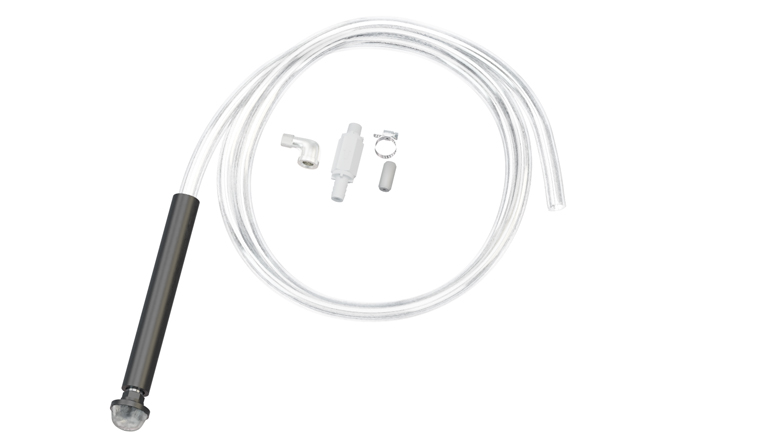
Model # 491403-A · Chemical Pick-up Assembly, EPDM (1/2" Tube)

Requirements
As an Upgrade

Unit with 1/4" check valve and 1/4" suction tubing

Ex. Check valves 491311, 491315, 491401, 491402, etc.

As an Add-On

Unit with an unused, plugged chemical port

Options

For Stronger Ratios or Viscous Chemicals
1/2" Chemical Pick-up Assembly (Viton)# 491404-A
1/2" Chemical Pick-up Assembly (EPDM)# 491403-A
491403-A
Warning! Read All Instructions Before Using Equipment!

Overview

This assembly features a higher volume check valve and thick 1/2" tubing, which allows venturi injectors to draw more chemical and create a stronger solution than a standard 1/4" chemical pickup assembly.  It also allows for a faster chemical draw rate using high viscosity (thick) chemicals.  Use this kit to replace a standard pickup assembly, or add a second pickup assembly to units with an unused chemical port on the injector body.  Available with EPDM or Viton check valve.
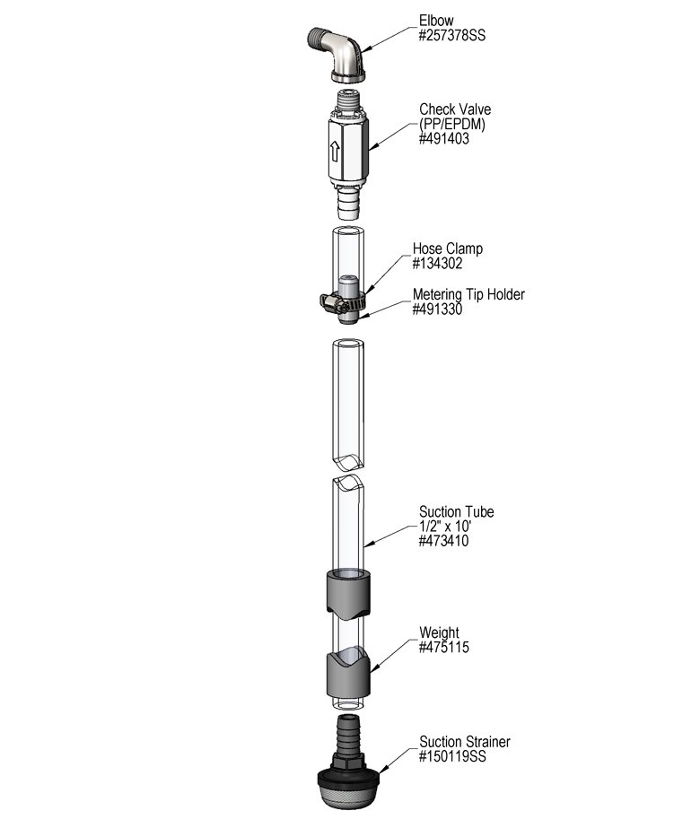
To Install (refer to diagram on next page)

As an Upgrade:

  1. Remove existing chemical pickup assembly from injector body.
  2. Note:  It may be necessary to remove the injector body from the back plate if you wish to replace the chemical pickup elbow.
  3. Attach new assembly in same position as original.

As an Add-On

  1. Note: This option is only available for specific units with an extra (plugged) injector body port for a second chemical pickup assembly.  Refer to the unit parts diagram.
  2. Remove port plug.
  3. Attach new assembly in the same manner as original.
  4. Note:  It may be necessary to remove the injector body from the back plate to rotate the elbow into position.

Set the chemical dilution ratio by installing the inline tip holder and a metering tip into chemical pick up tube. See chemical label for dilution ratio recommendation or consult your chemical supplier.

  • For the strongest possible chemical dilution ratio, do not install a metering tip.
  • The dilution ratios in the metering tip chart are based on chemical with a viscosity of 1CPS.
  • For water pressure other than the example, use the Metering Tip Selection Formula.
  • Due to varying chemical viscosity and applications, you may need to increase/decrease the tip size to get the best result.
  • Install a colored metering tip in the inline tip holder. DO NOT OVER-TIGHTEN
  • Splice tip holder into the chemical pick up tube as shown in the drawing. Use the hose clamp as shown in the diagram (certain units only). 
  • Once metering tip is installed immerse the chemical strainer into your chemical concentrate.
  • If necessary, cut suction tube(s) to length before attaching suction strainer.
491403-A.jpg
PREVENTIVE MAINTENANCE: When the unit will be out of service for extended periods, place chemical tube(s) in water and flush the chemical out of the unit to help prevent chemical from drying out and causing build-up. Periodically check and clean chemical strainer and replace if missing.