Lafferty Equipment Manufacturing, LLC

Installation & Operation Instructions

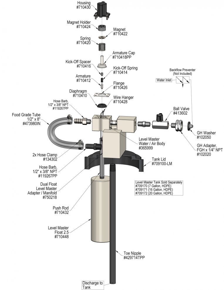
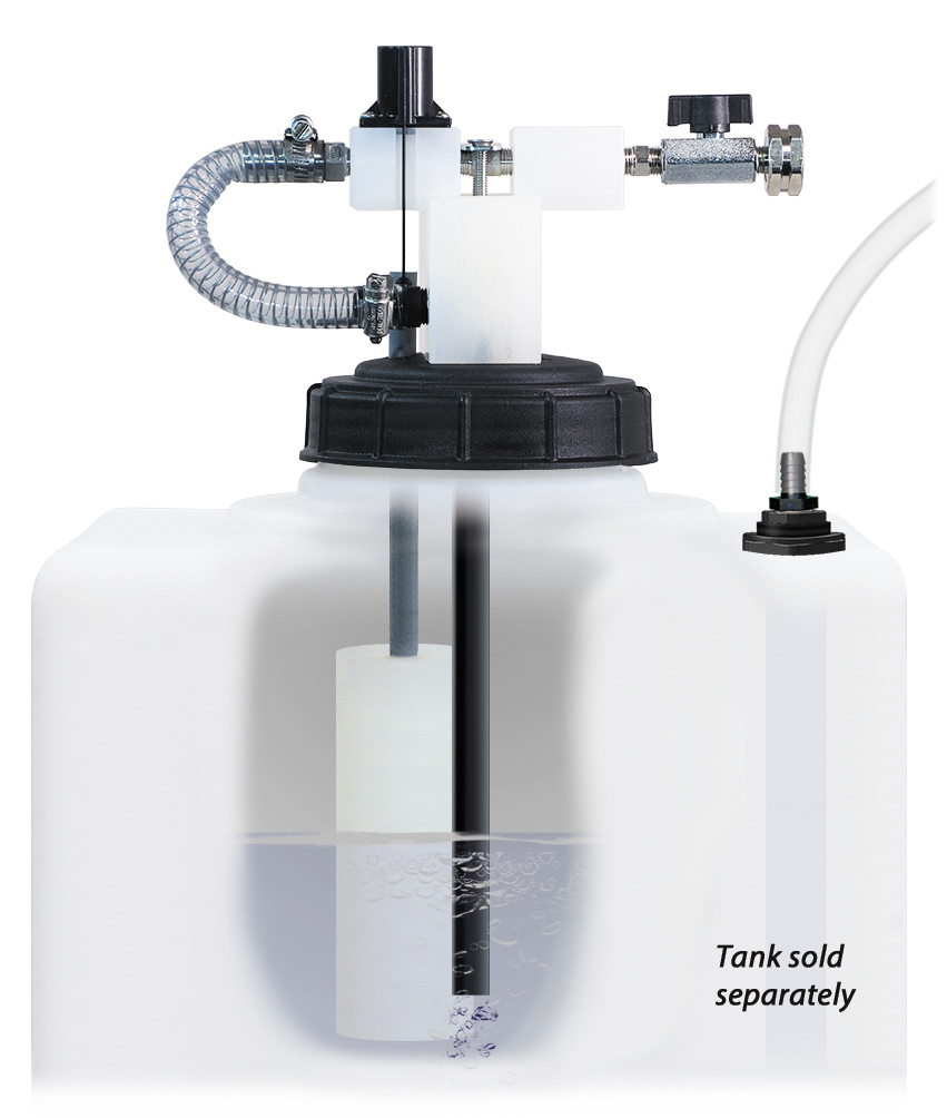
Model # 989330 · Static Water Tank Level Master™ (No Tank)

Requirements

Paired Level Master Tank See Options
Water Supply Up to 7 GPM @ 40 PSI
Water Pressure 125 PSI Max.

Options

Level Master Tank Sizes (Specify When Ordering)
7 Gallon# 709170
16 Gallon# 709171
20 Gallon# 709172
989330
Warning! Read All Instructions Before Using Equipment!

Overview

The Static Water Tank Level Master™ (No Tank) automatically maintains a constant supply of water in a paired tank (sold separately). When the water in the tank drops below a pre-set level, it is replenished using city water pressure (up to 125 PSI) and cycles continuously.

Safety & Operational Precautions

  • When connecting to a potable water supply follow all local codes for backflow prevention.
  • For proper performance do NOT modify, substitute nozzle, hose diameter or length.
  • Manufacturer assumes no liability for the use or misuse of this unit.
  • Wear protective clothing, gloves and eye wear when working with chemicals.
  • Always direct the discharge away from people and electrical devices.
  • Follow the chemical manufacturer's safe handling instructions.
  • NEVER mix chemicals without first consulting chemical manufacturer.

To Install (refer to diagram on next page)

Backflow prevention: Follow all local codes for preventing backflow into the water supply before installing / operating equipment.

  1. Position Level Master Tank on a level surface.
  2. Carefully unpack the lid / float assembly and thread on to tank opening.  Ensure that the float(s) are hanging freely.
  3. Connect the water supply. DO NOT TURN ON.

To Operate

  1. Securely attach the Level Master assembly to an empty tank.  Gravity will cause the float valve to automatically sit in the "down" position.  The float valve is now open.
  2. Completely open the water inlet ball valve to begin filling the tank.
  3. When the water in the tank reaches the fill level, the float will rise and shut off the water flow.

NOTE: The fill level is pre-determined by the length of the "push rod" attached to the float, which is intended to be used as provided.  If necessary, the float can be lowered 1/2" by partially unscrewing it from the push rod.

  1. Unit is now ready for use and will maintain the water level until the inlet ball valve is manually closed.
989330.jpg
Troubleshooting Guide
Problem Possible Cause / Solution
StartupMaintenance
A) Primary float will not activate (does not fill)
B) Primary float valve will not turn off (overfills or triggers secondary fail-safe float valve on double-float models)
1, 2, 3, 4
2, 3
5, 6, 7, 8, 9, 10
6, 7, 8, 9, 10
Possible Cause / Solution
StartupMaintenance
  1. Water ball valve not completely open
    • Completely open water ball valve.
  2. Water pressure too high
    • Install a water pressure regulator if pressure exceeds 100 PSI.
  3. Level Master body is not level
    • Install the Level Master on an even surface where the body (injector) is level to the horizon. Ensure that the Level Master will not become unbalanced as it fills.
    • If the body is not level, the float assembly may snag and prevent proper activation and/or deactivation.
  4. Secondary fail-safe float has been triggered (double float models only)
    • Manually reset the secondary fail-safe float valve (refer to operation instructions)
    • Inspect the primary float assembly before resetting the secondary float valve.  If necessary, troubleshoot the primary float assembly.
  1. Water strainer screen clogged
    • Clean inlet stainer screen; replace if missing.
  2. Physical blockage or interference is preventing the float from rising or falling
    • Ensure that the tank is on a level surface.
    • Ensure that the float, push rods, and metal clips are hanging freely without any interference.
  3. Float valve parts are dirty or defective
    • Clean or replace the affected parts (may require careful disassembly, refer to parts diagram).
    • Ensure that all parts are free of rust, grease, and loose metal chips.
    • Depending on the type of chemical used and other operational variables, regular cleaning and/or replacement may be required.
  4. Float valve diaphragm stretched out or damaged
    • Replace the float valve diaphragm.
  5. Scale build-up may have formed in the body causing poor or no flow
    • Follow Preventive Maintenance instructions below, using hot water and/or descaling acid.  When there is no flow at all, carefully remove fittings and soak entire body in descaling acid.
  6. Upward force has unclipped hanger from magnet holder
    • Carefully remove float housing and align wire hanger to grooves in magnet holder.
    • Pull down on wire hanger until you hear a sharp 'click' after the normal activation sound.
    • Wire hanger must be fully seated in magnet holder grooves, as shown below.
    • Float hanger seated correctly
PREVENTIVE MAINTENANCE: When the unit will be out of service for extended periods, place chemical tube(s) in water and flush the chemical out of the unit to help prevent chemical from drying out and causing build-up. Periodically check and clean chemical strainer and replace if missing.