Lafferty Equipment Manufacturing, LLC

Installation & Operation Instructions

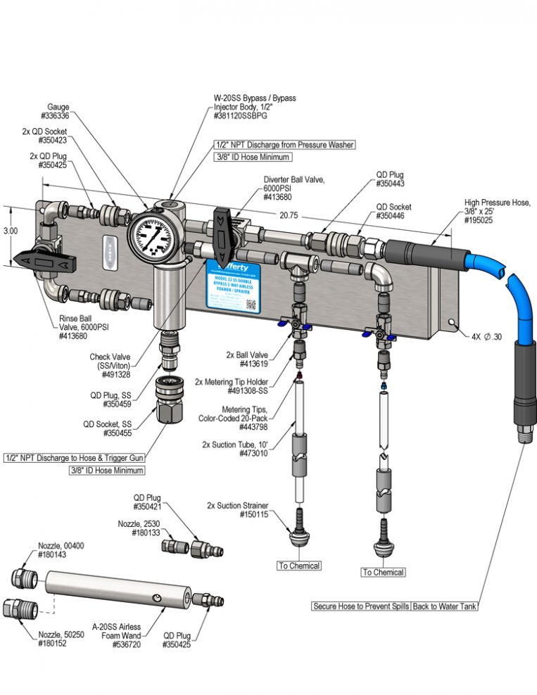
Model # 969762 · Model 22 SS Double Bypass 2-Way Airless Foam/Spray System (NO HOSE)

Requirements

Water Temperature up to 180°F
Pressure Washer 5.5 - 10+ GPM
Discharge Hose

3/8" or 1/2" ID

Up to 200' length

Options

Stainless Steel Hose Racks
Large Stainless Steel Hose Rack# 224150
Stainless Steel Jug Racks Available
Safe Flow Lid™ for 1 Gallon Jugs
Lid, Suction Tube, and Strainer# 709101
Pressure Washer Hose & Trigger Gun
HP 3/8" x 50' Hose & Trigger Gun Kit# 807069
Inlet Jumper Hose
Hose, 1/2" x 6', High Pressure# 195106
969762
Warning! Read All Instructions Before Using Equipment!

Overview

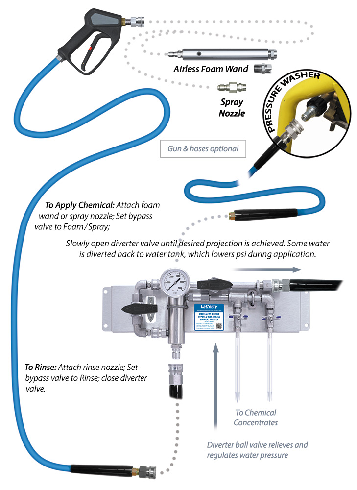
Designed for 5.5–10+ GPM pressure washers. The Model 22 SS Double Bypass 2-Way Airless Foam/Spray System features a diverter ball valve to control pressure, flow and foam throw distance. During chemical application, the diverter valve decreases pressure and flow incrementally the more it is opened, sending water back to the tank so the unit operates at 5 GPM or less. The stainless steel venturi injection system draws and blends two separate chemicals or two different concentrations of the same chemical into the water stream to create an accurately diluted solution. The solution then flows through the hose and gun to the airless foam wand which draws in atmospheric air to create and project wet, clinging foam on to surfaces up close or at distances up to 25 feet with interchangeable fan and zero degree nozzles. Quick connect the fan pattern sprayer nozzle to apply non-foaming chemicals. To rinse at full volume and pressure, close the bypass and diverter valves and switch to a rinse nozzle.

Safety & Operational Precautions

  • For proper performance do NOT modify, substitute nozzle, hose diameter or length.
  • Manufacturer assumes no liability for the use or misuse of this unit.
  • Wear protective clothing, gloves and eye wear when working with chemicals.
  • Always direct the discharge away from people and electrical devices.
  • Follow the chemical manufacturer's safe handling instructions.

To Install (refer to diagram on next page)

  1. Mount the unit to a suitable surface above the chemcial container.
  2. Connect pressure washer to the unit.
  3. Run diverter hose back to the water tank and secure it to prevent spills
  4. Connect discharge hose.

Set the chemical dilution ratio by threading one of the color coded metering tips into each chemical check valve. See chemical labels for dilution ratio recommendation or consult your chemical supplier.

  • For the strongest dilution ratio do NOT install a colored metering tip.
  • The dilution ratios in the metering tip chart are based on water thin chemicals with a viscosity of 1CPS.
  • Thicker chemicals will require a larger tip than the ratios shown in the chart.
  • Application results will ultimately determine final tip color.
  • Select the tip color that is closest to your desired chemical strength and thread it into the tip holder. DO NOT OVER-TIGHTEN.
  • Push the chemical tube over the check valve barb and place the suction tube in the chemical concentrate.
  • If necessary, cut suction tube(s) to length before attaching suction strainer.

To Operate

TO FOAM OR SPRAY AND CONTROL THE PERFORMANCE / THROW USING THE DIVERTER BALL VALVE

The diverter ball valve is used to relieve excess pressure/volume on pressure washers with flows greater than 5 GPM.  Excess water volume is diverted directly back into the water tank.

It is also used to reduce foam or chemical spray projection, and can also reduce rinse pressure and volume for more controlled close range applications. Higher pressure/GPM will foam larger areas more quickly.
 
  1. Remove the rinse nozzle and quick connect the foam wand or the chemical spray nozzle to your trigger gun as shown in the diagram. If your trigger gun doesn't have quick disconnects you will have to install them.
  2. Turn the by-pass ball valve to the "foam" position.
  3. Open one chemical ball valve (or if blending two chemistries open both)
  4. Hold the trigger gun firmly and direct the discharge in a safe direction. Pull the trigger and observe the pressure shown on the pressure gauge. (MAXIMUM recommended pressure 1800 PSI for Foaming/Chemical spraying, minimum will depend on hose length, longer hoses will require slightly higher pressure for venturi to operate)
  5. Slowly start opening the diverter valve until the pressure starts to reduce and the desired foam/chemical spray  and throw distance is achieved. (Can also be used to reduce the rinse pressure or volume.)
  6. Make final metering tip adjustments based on application results. Try the next larger sized metering tip until the results are acceptable.
  7. Repeat step 3 for additional chemicals

TO RINSE

  1. When foaming/spraying is completed, release the trigger.
  2. Replace the airless foam wand or low pressure spray nozzle with the original pressure washer rinse nozzle. 
  3. Close the chemical ball valves and diverter valve and open the by-pass ball valve.
  4. Rinse the work surface as you normally would and rinse before the chemical dries.
  5. If the unit will not be used for a period of time it is BEST to draw fresh water through the pick up tube(s) to prevent chemical from drying inside the components.

Metering Tip Selection

Metering Tip Color
OZ/Min
Dilution Ratio 
@ 4.0 GPM
Brown
0.56 914:1
Clear
0.88 582:1
Bright Purple
1.38 371:1
White
2.15 238:1
Pink
2.93 175:1
Corn Yellow
3.84 133:1
Dark Green
4.88 105:1
Orange
5.77 89:1
Gray
6.01 85:1
Light Green
7.01 73:1
Med. Green
8.06 64:1
Clear Pink
9.43 54:1
Yellow Green
11.50 45:1
Burgundy
11.93 43:1
Pale Pink
13.87 37:1
Light Blue
15.14 34:1
Dark Purple
17.88 29:1
Navy Blue
25.36 20:1
Clear Aqua
28.60 18:1
Black
50.00 10:1
No Tip  7:1
The dilution ratios above are approximate values. Due to chemical viscosity, actual dilution ratios may vary.

Formula

GPM × 128 ÷ Desired Dilution Ratio = oz/min

  • See Unit Flow Rates chart for GPM
  • Use 20 for 20:1 dilution ratio, 30 for 30:1, etc.
  • Match calculated ounces per minute (oz/min) to nearest oz/min in Metering Tip Selection chart.

UNIT Flow Rates

Water Flow Rate 
GPM PSI Shown on Gauge
During Operation
2.0 300
2.5 469
3.0 675
3.5 919
4.0 1200
4.5 1519
5.0+ 1875+

Online Metering Tip Calculator Help

https://www.laffertyequipment.com/tools/metering-tip-calculator/

Unit Flow Rate = GPM @ PSI Shown on Gauge
• Example:  4.0 GPM @ 1200 PSI
Actual Water Pressure = PSI Shown on Gauge
• Example: 1200 PSI

969762.jpg
Troubleshooting Guide
Problem Possible Cause / Solution
StartupMaintenance
A) Unit will not draw chemical.
B) Does not foam properly
C) Using too much chemical
1, 2, 3, 7
1, 4, 5, 7
6
8, 9, 10, 11, 12, 13
8, 9, 11, 12
Possible Cause / Solution
StartupMaintenance
  1. Water volume too low
    • See requirements.
  2. Water inlet clogged
    • Clean the water inlet. DO NOT DRILL OUT
  3. Hose size too small
    • MUST be 3/8" ID hose, minimum
  4. Ensure chemical is recommended for foaming and/or the application
    • Refer to chemical manufacturer.
  5. Dilution too weak / Chemical is very thick.
    • Install larger metering tip or remove metering tip.
  6. Dilution too strong / No metering tip installed or wrong metering tip installed
    • Install a metering tip or install a smaller metering tip
    • If the exact dilution ratio cannot be achieved with metering tips, pre-dilute the chemical with water before drawing it into the injector for final dilution and application
  7. Hose too long
    • Use a shorter discharge hose to alleviate back pressure on the injector
    • The allowable length of hose varies based on individual pressure washers and equipment setups. 200' max recommended hose length between injector and nozzle. Longer hose could affect dilution ratios.
  1. Chemical check valve stuck, clogged, loose or failed
    • Clean, tighten or rebuild.
  2. Chemical strainer or metering tip blocked
    • Clean or replace chemical strainer and/or metering tip.
  3. Chemical tube stretched out where tube slides over check valve or pin hole/cut in chemical tube (sucking air in) which reduces chemical intake. Chemical tube not immersed in chemical or depleted.
    • Cut off end of tube, replace tube or immerse tube in chemical
  4. Discharge nozzle is wrong size
    • Install correct nozzle (see parts drawing)
    • Use only provided nozzles/wands for chemical application
  5. Chemical build-up or hard water scale may have formed in the foam wand or injector body causing poor or no chemical pick-up
    • Follow Preventive Maintenance instructions below, using hot water and/or descaling acid. When there is no draw at all, carefully remove inlet fitting and chemical check valve. Soak injector body and or foam wand in de-scaling acid.
  6. Bypass ball valve open (Bypass models only)
    • Close bypass valve.
PREVENTIVE MAINTENANCE: When the unit will be out of service for extended periods, place chemical tube(s) in water and flush the chemical out of the unit to help prevent chemical from drying out and causing build-up. Periodically check and clean chemical strainer and replace if missing.